How to program the DX7
Understanding and applying the concepts of digital FM synthesis
(From "Keyboard Mag", June 1985)
Synthesizers have a kind of aura for the layman — exciting, but exotic and perplexing. Most experienced synthesizer players, on the other hand, can quickly become comfortable with a new instrument, zipping around the front panel as they edit the factory patches to their own taste. Even for players, though, the Yamaha DX7 has some of this aura of mystery. They like the way it sounds, but they've heard that it’s impossible, or at least very difficult, to program.
There are several reasons why people feel this way. First, they're dealing with a different type of synthesis than they're used to. The concepts of FM (frequency modulation) aren't familiar, the DX envelopes are not the typical ADSR envelopes, and features like linear and exponential keyboard level scaling may initially be difficult to grasp. Having to enter all the data for a patch in numerical form rather than turning knobs can also be a stumbling block, but more and more instruments these days operate in a similar way, even if the synthesis techniques being used are different.
Three years ago, when we were first creating the factory patches for the DX7, we were able to do 420 patches in a very short time, with no manual and starting with only sine waves in the instrument. There’s no reason why anybody else shouldn't be able to do the same. Approaching any instrument for the first time, whether it’s a Minimoog or a Buchla, means learning how it works. You don’t just walk up to it and set up a perfect trumpet patch. You have to start by learning what rotating a pot means. By now we’ve all become used to certain standard configurations. If you're an Oberheim person you'll be able to get comfortable very quickly when you move from an OB-Xa to an OB-8. You'll know where you have to set the pots to get a certain envelope. Working with the DX7 means discarding some ideas that are probably familiar to you from analog synthesis and substituting other ideas. But it's not inherently any more confusing — it’s just different.
One comparison that I like to make is that if you want to knit a sweater, you can take out large needles, and you'll be done very quickly. But if you want to get the little flowers on the pockets, all the fine detail, you’ve got to use smaller needles. The DX allows you to take out those smaller needles and really fine-tune the details of the sound. So okay, your sweater is going to take a little longer to knit. As we learn to take full advantage of the potential of the instrument, the sounds we're programming can become more intricate.
Most people, when they start programming the DX, take one envelope and copy it across to all six operators. A sa result, the whole sound has one envelope. There’s no intricacy in that area at all. The copy function is useful for speed, or for when you’re doing things like organ sounds, which have an inherently simple envelope, but when you start to get into higher levels of programming, you'll want to create an individual envelope for each sine wave. Each sine wave should have a different function as part of the composite sound.
Getting started
In talking about the DX, the language we'll be using doesn't use terms like ‘filter’ and ‘sawtooth.’ We have to use a different language. To begin with, there are six sine waves inside the instrument. Each of those sine waves can be one of two things: a carrier or a modulator. A carrier is something that you can hear. A modulator you cannot hear; it alters the tone color of the carrier.
Looking at a carrier, we see that we have control of three things. First, we can control its overall volume, using the output level parameter. Second, it has an envelope generator, which shapes this volume. If we relate the DX to what we’re familiar with from analog synthesis, we can say that the envelope generator of a carrier is similar in function to the envelope generator of a VCA.
And third, a carrier has a specific pitch, which we control using the coarse frequency, fine frequency, and detune parameters.
Coarse frequency breaks the frequency spectrum up into 32 segments corresponding to the natural overtone series, starting an octave below the fundamental. The numbers you'Il see in the display (.50, 1.00, 2.00, 3.00, and so on) represent frequency ratios. We don't have space here to explain overtone theory in detail; if you re not sure how it works, please goto your local public library and check out a textbook on the nature of sound. You can also think of these numbers as corresponding to organ pipe footage, if you re used to that terminology. 0.50 is a 32' pipe, 1.00 is a 16', 2.00 is an 8', 4.00 is a 4', 8.00 is a 2'. The settings in between are smaller intervals; 3.00 corresponds to the 5-1/3' drawbar on a Hammond organ, which is an octave and a fifth above the 16' drawbar.
The fine frequency setting breaks each of these divisions into 100 smaller steps. And detune breaks up the smaller divisions into 15 subdivisions (from +7 to -7). Detuning is very subtle; people try to use it the way they do on an analog instrument, to create chorusing. But there's a better way to do chorusing, which I'll mention below. Detuning is most often used for fine-tuning a high harmonic; its other effect is to introduce a slight timbral shift, a wah-wah effect. There are ways of using detuning at specific frequencies to add to the chorusing effect, but it shouldn't be the only approach you use for chorusing.
In the normal mode of operation, the frequency of the sine wave tracks the keyboard. You can also take it into a fixed frequency mode, in which it does not track the keyboard at all, but remains the same from one end of the keyboard to the other. In this mode, you can set it anywhere from 1Hz (one cycle per second) to 9,772Hz. Fixed frequency carriers and modulators are used for a lot of different things — adding grit to a tone, adding fixed-frequency formants to vocal sounds, adding the sound of a pick on a guitar. You can create a chorusing effect by putting the carrier in fixed-frequency mode below 3Hz. All of the harmonic structure created by the modulators, which we haven t spoken about yet, will chorus at the frequency of the carrier as the phase angle of the sine waves changes.
Modulators have the same control parameters as carriers, but they are used in a different way. A modulator is used to change the timbre (tone color) of a carrier. Its output level determines the amount of change; the more output we have from the modulator, the brighter the sound will be. If you like, you can think of the output level control of the modulator as similar to the cutoff frequency control on a lowpass filter. Instead of moving the cutoff point, we now move the output level of a modulator to change the sound from mellow to bright. The envelope of the modulator is more or less equivalent to the VCF envelope on an analog instrument.
Because the frequency of the modulator is independent of the frequency of the carrier, there will be a frequency relationship between the two. This relationship determines the overtone structure of the sound, and is roughly equivalent in function to a very complex and flexible waveform selector. Note that having a modulator modulate the frequency of a carrier is not the same as adding the two waveforms; the mathematical relationship is more complex than addition, as Figure 1 snows. This frequency modulation is what gives FM synthesis its name, and its characteristic sound.
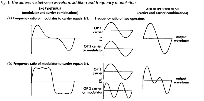
If the carrier and modulator are on the same frequency, the sound of the carrier will be equivalent to a sawtooth wave (Fig. 1a). The high harmonics on this are not as strong as those on a sawtooth on an analog instrument; we have to add more modulators to get that bright a sound. But it is a wave with all the overtones, so it is a basic sawtooth sound. When we raise the output of the modulator one octave above the frequency of the carrier, we have a square wave (Fig. 1b). Taking the frequency of the carrier above the frequency of the modulator gives us various pulse waveforms.
To hear this, choose a memory slot you don't want to keep and start with voice initialization in the function mode. When you see “VOICEINIT?”’ inthe LCD, press “‘yes”’ twice. This kicks you into the edit mode, ready to program from scratch. Raise the output level of operator 2 to 72. When you play the keyboard, you should hear the basic sawtooth waveform. Now raise the coarse frequency of operator 2 from 1.00 to 2.00. This will give you a square wave. Lower operator 2's frequency back to 1.00 and raise operator 1 from 1.00 to 2.00, 3.00, 4.00, and so on. At each step you will hear a narrower pulse waveform. There does come a point of no return, where the frequency of the carrier starts to override, and the waveform turns into something else. But this is how we get into oboes. A nice oboe might be achieved by setting the carrier to a frequency of 4.00 with the modulator on 1.00.
So that’s the ABC of programming the DX. The carrier determines the volume of the sound, the modulator’s envelope creates the timbral movement in the sound, and the frequency relationship between the two determines the waveform. Incidentally, as long as you stick to whole-number frequency relationships, you’re limiting the scope of the instrument. Non-whole-number relationships will give you ring modulator sounds and other types of overtones that can be characteristic of some acoustic instruments, not to mention instruments that never existed before. And everything we’ve said so far has used only two sine waves! Piling up more modulators will give you overtones that are more and more complex.
Algorithms
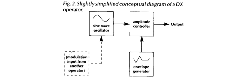
Usually, people's mind just turn off when they hear the word '‘algorithm’, because they assume it’s something too complex to deal with. But tn fact the concept is very simple and straightforward. The term ‘operator’ seems mysterious too. You can think of an operator as a unit or module that includes a sine wave oscillator (either modulator or carrier), an envelope generator, and a VCA (see Fig. 2).
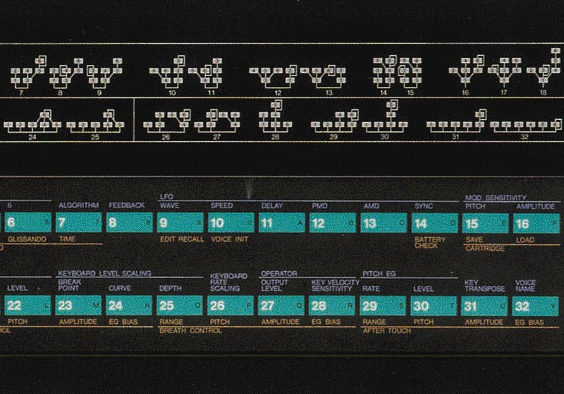
In fact, these are not discrete components, the way they would be on an analog synthesizer. They all exist as software inside a microprocessor. But you don't need to worry about this in order to understand how they work. The front panel graphics on the DX show exactly how the operators in any algorithm are patched together. All you have to remember is that the bottom row of operators are the carriers, and those above them are modulators. Operator one is always a carrier. The modulators control the timbre of the carriers to which they are connected by vertical or diagonal lines.
I explain algorithms at my clinics by building a sound for people on the blackboard. Generally I do this before I even mention the word ‘algorithm’, so as not to alarm them. Let's say we want to make an electric piano sound. By analyzing the sound we're aiming for, we can figure out what algorithm to use. For now, tnough, don't worry about the principles behind this kind of analysis. Just take a look at algorithm 26 (Fig. 3). It has three carriers, each of which will make its own contribution to the finished sound.
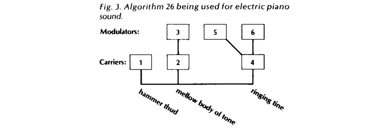
Operator 2 is a carrier that has a single modulator (operator 3). We ll use these two to make the body of the tone — the mellow, slowly decaying sound. The carrier with two modulators (operator 4) is going to make the bright, complex attack sound of the tine.
Both the carrier and the modulators here will have higher frequencies and faster decaying envelopes. The second modulator on that carrier will create a ring-modulation effect on the left half of the keyboard, so that the left hand will be distorted while the right hand will be pure. (This is done using the keyboard level scaling feature, which we'll talk about a bit more below). That particular modulator will be on a strange frequency. The one carrier by itself will be on a fixed frequency of about 97Hz. When we give this a fast, knocking envelope, it will create the thud of the hammer hitting the tine. Put the three elements together, and presto—electric piano!
In order to get the touch response of the electric piano, we need to set the key velocity sensitivity for the various operators. There should be a great deal of velocity on the hammer thud (operator 1),so that when we play softly we don’t hear it. We would put only a moderate amount, maybe 2 points, on the carrier that is making the body of the sound, and only 1 point on its modulator. For the tine, we could play around with it. Maybe we don’t want the tine at all when we play softly, or maybe we want some of the carrier sine wave without its modulator. It's amazing how totally you can change the character of a sound using the key velocity sensitivity.
This illustrates how each of the carriers in an algorithm makes its own contribution to the sound. To take an even simpler example, look at algorithm 32, in which all six operators are carriers, with no modulators at all. We can assign the first one a frequency of 1.00, the second a frequency of 2.00, and so on — 3.00, 4.00, 5.00, and 8.00 for the last one. This gives us six of the drawbars on an organ. (Obviously, the effect will be more realistic if you pive all six operators the same instant-on, full sustain, instant-off organ envelope, but you might experiment with giving some of them a bit longer attack and release than others). Adjusting the output levels of the operators is now equivalent to moving the drawbars in and out. You add in one sine wave at a time until you get the organ sound you want.
We could give lots of other examples, but by now the idea should be clear. You begin by creating a mental map of the sound you want to create. In some cases this might mean thinking about the mechanical operation of the instrument you're trying to imitate; in other cases the process might be more abstract. Once you have this map in mind, you look across the DX’s algorithm chart until you find an algorithm that matches it. Somewhere down the road you may find that you neglected to think about some aspect of the sound, because of which you may not be able to get it with that algorithm. So you go back, choose another algorithm, and start over.
If you re curious, the term ‘algorithm’ is borrowed from computer programming. An algorithm is a algorithm (often in the form of a flow chart) for solving a problem. The reason this term is appropriate for the DX is that the instrument does not actually have six separate sine wave generators for each of its 16 voices. In fact, it doesn't even have 16 voices; all 16 of the notes that are playable from the keyboard are being generated by one microprocessor. This uses various algorithms that instruct it how to construct a single composite sound wave. One way to think about this is that the way the computer data are being shuffled around the microprocessor by the algorithm is similar to the way voltages are routed through a modular synthesizer using patch cords. A particular configuration of patch cords is a kind of analog algorithm.
Once in a while somebody raises the question whether the existing 32 algorithms in the DX7 are really enough to create all the kinds of sounds we can imagine or want. There are several ways to answer this. Most general users, I find, can barely handle where the instrument is at right now. On the other side of the coin, I hope I'll have the opportunity in the future to work with Yamaha to develop an even more powerful instrument using the same FM technology, an instrument that those of us who spend all of our time programming can go totally nuts with.
And at the same time, I know that I haven't even come close to tapping the potential of the instrument as it stands right now. Every time I sit down at the DX, I learn something new.
The Envelopes
The envelopes on the DX are a completely new approach. We've gotten used to the standard ADSR, so let’s compare the two. On the ADSR, we have no control of the destination of the attack segment (unless the envelope output can be inverted, in which case we can choose one of two destinations). The attack always goes to the same point; we can only control its speed. We do have control of the next destination. We call it the sustain level. We can control how fast or how slow we get to the sustain level, and we call this the decay rate. Then when we take our finger off the key, the envelope is always going to go back down to zero, so again we have no control of the destination. We control only the rate of speed, using the release control.
This is the system that we've come to accept. But the Japanese sat back and said, “No, we think there is another approach to this concept.”’ They gave us what are called levels and rates. Envelope levels are actually controllable destination points. Instead of having one controllable destination, called sustain, we now nave four. Once we have set these levels, we then go on to say how fast we will get to each destination, using the four rate controls.
There are seven envelope generators on the DX7, one for each of the sine waves and a seventh for pitch. Both levels and rates can be set anywhere between 00 and 99 for each of these. For the levels, 00 is low and 99 is high, while for the rates, 00 is slow and 99 is fast, just like on a car's speedometer. In using the DX envelopes, you need to be aware that time is equal to distance divided by rate of speed.
That is, T=d/r
What this means is that for any given envelope rate, if you move the level closer to the previous level (which cuts down the distance between them) it will take less time for the envelope to reach the new level. Another way to look at it is that the rate setting actually determines the angle or slope of the envelope segment; lower rate settings approach closer to the horizontal. Since the angle is constant, when the levels are closer together vertically they will also be closer together on the horizontal (time) axis.
What's more, the operator’s output level control interacts with its envelope settings.
When you reduce the output level, you are actually lowering all four envelope level settings in some proportion controlled by a formula located inside the computer. So lowering the output level of an operator will speed up its entire envelope. One consequence of this is that if one of your patches sounds too loud in comparison to another, you shouldn’t just crank down the output of the loud one. Instead, ask yourself why the other one is so soft. In general, the output level of at least one operator within each patch should be set to 99, and one of the levels of each envelope should also be set to 99. If you don’t do this, you re not taking advantage of the full resolution potential of the envelope or the full signal-to-noise ratio of the instrument.
Another phenomenon you should be aware of is that if any of the envelope rates, either carrier or modulator, is set to 99 and there is a difference between that level setting and the previous level setting, you will get a click in your sound. This is because the envelope will move instantaneously from the old level to the new one, producing a sharp rising or falling edge in the waveform. Even in the case of percussive instruments with fast attacks, you don't usually want to set rate one to 99, because this will put a click in the attack. A setting of 97 or 98 will make a more realistic sound. After all, in an acoustic instrument, no matter how percussive, it takes several milliseconds for the vibrating object to be set in motion.
Setting an envelope level below 50 can create problems on the DX in one specific situation. Let’s say we want to set up a delayed envelope, in which the sound doesn't start immediately with the keystroke but comes in several seconds later. I'm not talking about a crescendo, which would be a gradual rise caused by a slow rate, but rather a period of silence followed by a relatively sudden rise. The way to get this is to set level one to 50, level two to 99, and level three to whatever sustain setting we want. (Always set your levels first, and then set the rates.) Now the setting for rate one will determine how long it takes the envelope to rise to 50, while rate two will be the actual audible attack. A level of 50 is still very nearly inaudible, so this will work fine. If you go much below 50, you'll get into some random problems that are beyond the scope of this article.
On the pitch envelope, which is the same for all six operators, the level must be at 50 in order for the keyboard to be sounding concert pitch. Above 50 is sharp, and below 50 is flat. The pitch envelope is useful for adding very slight pitch shifts to the attack and release of some sounds. When I went after my violin sound, I took into account that the bow has a great deal of friction, which pulls the string to one side before it starts vibrating. So the pitch of the string bends before it gets to its basic frequency. When I applied that concept by giving the string patch a very fast bend flat, then sharp, then back to pitch, it sounded much more realistic.
Each sound may require its own type of pitch envelope. When you look at an electric piano on a tuning meter, you find that it starts sharp, and as it dies away it also falls flat. So if you really want to sound like the original instrument, you should add a slight pitch envelope.
The pitch envelope can also be useful for special effects. For example, take the timpani sound from the original DX voice library. Go to level three on the pitch envelope and drop it down to about 35. Go to level four and raise it to about 70. Now play one note and hold your hand on the keyboard. You should hear the kettle drum drop in pitch. But when you play the same key with a staccato touch, lifting off it immediately, you should hear the kettle drum rise in pitch. It’s as though the timpani player were using his tuning pedal to stretch or relax the drum head after striking it. This is a drastic use of the pitch envelope, but it illustrates one fact about the DX envelopes that you should be aware of: when you lift the key, the envelope immediately begins moving toward level four at rate four, from whatever point it is currently at.
Incidentally, a rising envelope segment on the DX will take about 90 seconds to move from level 00 to level 99 if the rate is set to 00. A falling segment takes 3½ minutes. So if you set all the values to their greatest extreme, you'll get about a 10-minute envelope.
Programming Hints
I'm surprised sometimes to find that people don't understand the value of turning operators on and off using switches 1 through 6 in edit mode. When you are in the edit mode, the row of six 1’s in the LCD display gives you the status of these switches. Going back to our example of algorithm 26, the electric piano sound, we can switch off operators 1 and 4, which are both carriers, in order to hear the sound of operators 2 (carrier) and 3 (its modulator) by themselves. The status of these switches is not stored as part of a voice definition; they are always set to ‘on’ when you call up a patch. IF you don’t want to hear a given operator, you must set its output level parameter to zero.
Playing with these switches will help you learn now the sounds in the DX are built. This is the first step in learning to make minor edits in the factory patches. If there’s a patch you'd like to change the timbre of, call it up and start turning the sine waves on and off one at a time. Note that turning off a carrier will also silence any modulators attached to it (unless they are also modulating another carrier that is still switched on, as with algorithms 19 through 25). When you find the operator that is creating the aspect of the timbre you want to affect, you can raise that operator's output level to make that aspect of the sound brighter, and so on.
As you begin using these switches to listen to portions of a sound you re working on, you will quickly run into one minor annoyance, Let's say you re setting the frequency for operator 5. In order to make sure you've got it right, you switch operator 5 off for a moment, to hear the rest of the patch, and then switch it back on. At this point, the data entry slider is no longer set for operator 5. The LCD display confirms that you are now editing the frequency of operator 6! This happens because the operator select switch can only call up operators that are switched on. There is a way around this, however. Before switching the operator off, switch to one of the global edit parameters (7-15 or 29-32), for which there is no operator number in the LCD display. Now you can switch the operator off and on again, and when you return to the parameter you were editing, it will still be set to the same operator as before.
lf you want to get into some fun and games with programming, you can use the system-exclusive facility of MIDI not only for sending entire patches to other DXs, but for sending portions of a patch. Once you ve toggled the system information control (function 8) to ‘available,’ anything you touch on the front panel will be sent. You can send, for example, part of an envelope of a guitar over to a string sound on another DX.
Because the DX always remembers the last function control you touched, it’s possible to get yourself into trouble during a gig and not know why. Let's say the last thing you touched before you went to memory select was the master tune function. At this point, no matter what patch you call up from memory, the data entry slider is still a master tune control. If you nudge it, you'll go out of tune. You can also use this situation to your advantage. Touching portamento time before returning to memory select makes the slider a portamento control that you can play with interactively.
Performance Functions
Two controls that people often don’t understand how to use are controls 15 and 16 in edit mode — the pitch and amplitude sensitivity settings. When pitch sensitivity is set to zero, you can try to introduce pitch modulation all day long, from the breath controller, the mod wheel, the LFO, wherever, and nothing will happen. When it’s set to 7, you Il get maximum response from all the sources of modulation. The amplitude sensitivity works the same way (These controls don't affect the volume foot pedal input or the pitch-bend wheel).
People who don't understand controls 15 and 16 are constantly changing the settings of their performance functions. This isn’t necessary. By setting 15 and 16 properly, you can leave the performance functions set the same way at all times and get a full spectrum of modulation routings, which can be different for each preset. Here's how I setup my functions:
Mod wheel: range 50, pitch off, amplitude on, EG bias on. Foot controller and breath controller (same settings): range 99, pitch off, amplitude off, EG bias on. Aftertouch: range somewhere between 40 and 60 depending on how hard you push, pitch on, amplitude off, EG bias either on or off.
Your vibrato will now be on the aftertouch, which is nice for things like violin sounds. The key velocity will control the attack of the bow, and the aftertouch will control the vibrato, giving you a great deal of expressive control. There is no longer any need to use the mod wheel for vibrato. With the settings shown above, the mod wheel will control wah-wahs and tremolos. Your foot pedal and breath controller will be making sounds louder and softer and brighter and mellower. Plug the foot pedal into the modulation input jack, never into volume. The reason for this is that volume pedal information is not sent through MIDI, and modulation is. If you're talking to rack modules or other DXs, you want the pedal to be active.
Using control 16, you can determine the amplitude sensitivity amount separately for each operator. If the carriers have amplitude sensing, the pedal will be a volume pedal. On the next patch, you might set the modulators to have amplitude sensing, making it a wah-wah pedal. On a third patch, it might be a mix control for one of the components of a sound, such as a sub-octave oscillator or a percussive attack.
When the EG bias for a controller is on, the controller overrides the controller envelopes for which amplitude sensitivity has been programmed. This will be a complete override if the amplitude sensitivity is set to full on (3), while at lower levels (1 or 2) the internal envelope will still have a reduced but audible effect. The full-on setting is especially useful for wind instrument sounds, because you can control their amplitude from the breath controller, giving realistic articulations. You can hold down a note on the keyboard and get no sound until you blow into the breath controller. When EG bias is off but amplitude or pitch control and sensing are on, a controller becomes an LFO amount control.
Level & Rate scaling
Keyboard level scaling is another feature of the DX that people sometimes don’t know how to make the best use of. Using level scaling, you can create a loudness curve for each operator along the length of the keyboard. In extreme cases, this can be used for split keyboard effects: one set of operators (maybe 1, 2, and 3) is audible at left left end of the keyboard, but these are “scaled down’ at the right end, removing them from the sound, and another set (4, 5, and 6) is scaled up. With algorithms like 5 and 6, you can even get three separate sounds — one at the left end, one at the right end, and one controlled by an amplitude foot pedal.
More subtle effects are the rule, however. if you like, you can think of scaling as equivalent to the keyboard tracking on an analog filter. Many acoustic instruments sound different in various parts of their range, and level scaling is used to raise or lower the output of modulators to mimic the harmonic content of these instruments. In the example we gave earlier of the electric piano algorithm, level scaling is used to introduce a distorted ring-modulation effect in the left hand. This distortion is similar to what you hear when you hit a low key hard on an electric piano.
When creating a new voice from scratch, you'll probably find it helpful to play within a restricted range at the center of the keyboard as you are setting your envelopes and operator levels and frequencies. Once you have the sound you want in this range, it is simpler to scale the operators up or down as needed in the outer ranges. Note that the maximum output of an operator is always going to be 99, so if you have the basic level set at 98, you will have only 1 unit of amplitude left when you select a positive-going curve.
Rate scaling is simpler in operation than level scaling; it is very similar to the keyboard tracking parameter on the envelope generators of other synthesizers. It makes the envelope faster at the right end of the keyboard than at the left. The keyboard is divided into groups of three notes, each of which will have a slightly shorter envelope than the group to its left. In order to see how useful this is, you can take an expensive high-tech acoustical analysis tool that everybody has, called a stopwatch, and find out for yourself how long a note lasts at the bass end of a piano as opposed to the treble end. You'll find that a bass-register note lasts for about 40 seconds, while a treble note dies away in only 8 seconds or so.
Now let's use this information to create a piano envelope. Use a fast attack — not 99, remember, but still fast. Then drop down 6dB or so at a fairly quick rate, to a level 2 setting of 89. Set level 3 to zero, and set rate 3 so that the total envelope time is about 40 seconds. We now have the overall picture of the piano envelope in the left hand. Next, raise the rate scaling until the envelope in the top octave is about 8 seconds, and you'll have the correct rate scaling for the piano.
Conclusions
I hope you've found this discussion of DX programming helpful. As I said earlier, after several years of intense work with the instrument, I still feel that I’ve barely tapped its potential. In the near future, acoustic research will be able to tell us very precisely which envelope characteristics and harmonic elements cause acoustic instruments to sound the way they do, and we will be able to use instruments like the DX to create whole new classes of sounds. What would a fifty-foot acoustic guitar made out of glass sound like? By grafting a slowed-down guitar envelope onto the harmonic spectrum of glass, we can play such an instrument. Currently, sampling instruments are gaining in popularity, because they give us a better handle on this type of sound than analog synthesis did. But sampling real sounds, even when you can process the data afterward, is still a one-dimensional way of doing things; It has some stringent built-in limitations. In the long run, I feel, it is instruments like the DX that will give musicians the greatest freedom to discover their own sounds.
By Bo Tomlyn, as told to Jim Aikin